
⭐Wire Trailer Diagram⭐ Multiracial singles
Trailer Wiring Reference Chart Trailer Wiring Reference Chart Loading. 75 view (s) 2 min read Trailer Wiring Reference Chart Trailer wiring can be confusing so we have put together color-coded diagrams to help you out. If you have any additional questions or need any help don't hesitate to contact us. by Teresa Wroblewski Posted in: Towing

Gooseneck Trailer Wiring Diagram Gallery Wiring Diagram
The term "gooseneck" refers to the flexible tube-like structure that is used to connect a trailer to a towing vehicle. This wiring system allows for the transfer of electrical power, including brake lights and turn signals, from the towing vehicle to the trailer. Understanding the wiring of a gooseneck is essential for safe and reliable towing.
Gooseneck Trailer Wiring Schematic
Trailer Wiring Diagram and Installation Help Chapter 7 Equipping Your Vehicle with Proper Trailer Wiring Any vehicle towing a trailer requires a trailer wiring harness to safely connect the taillights, turn signals, brake lights and other necessary electrical systems.
Gooseneck Trailer Wiring Harness
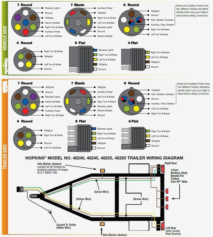
5 Pin Trailer Wiring Diagram 6 Pin Trailer Wiring For heavier towing jobs, many use gooseneck trailers. Those are generally put in the bed of a truck and use a 6-pin trailer wiring adapter. 6-Pin trailer wiring uses the same color code as 4- and 5-pin trailer wiring, adding one more function. This wire is black and adds auxiliary power.
wiring diagram for featherlite gooseneck
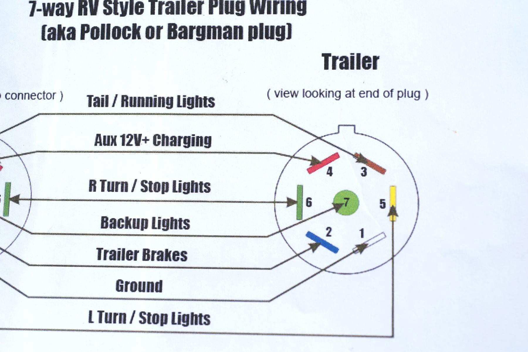
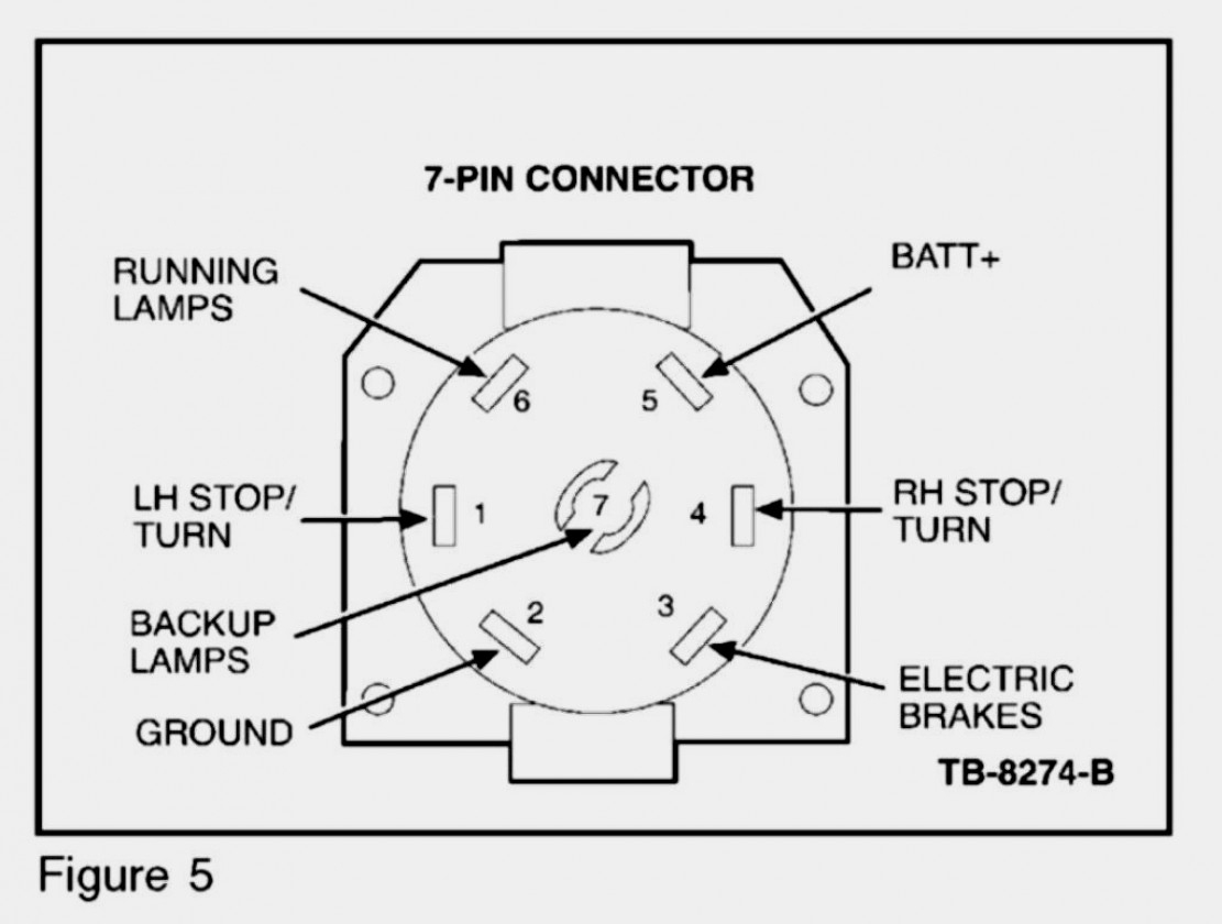
These diagrams will help ensure you wire your PJ Trailer using the correct standard for either a 4-way and 7-way plug wiring systems. 4-Way Plug Wiring 7-Way Plug Wiring Trailer plug connector diagrams for electrical towing connectors. View diagrams for our 4-way, 6-way & 7-way plugs.

Corn Pro Gooseneck Wiring Diagram Wiring Diagram
stamped in the aluminum of the gooseneck street side of the trailer.) Record all 17 digits of the VIN. See Fig. 1 2. Date trailer was originally purchased and the name of the dealer purchased from. Also known as the Dealer of Purchase. 3. Part number and/or description of the failed or problem component and photos of the failed item(s).
Wiring Diagram For Gooseneck Trailer Hitch What Is Paintcolor Ideas
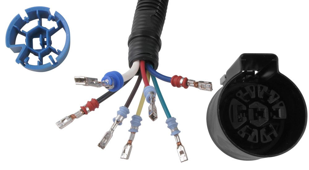
Various connectors are available from four to seven pins that allow for the transfer of power for the lighting as well as auxiliary functions such as an electric trailer brake controller, backup lights, or a 12V power supply for a winch or interior trailer lights.

Trailer Brake Controller Wiring Diagram
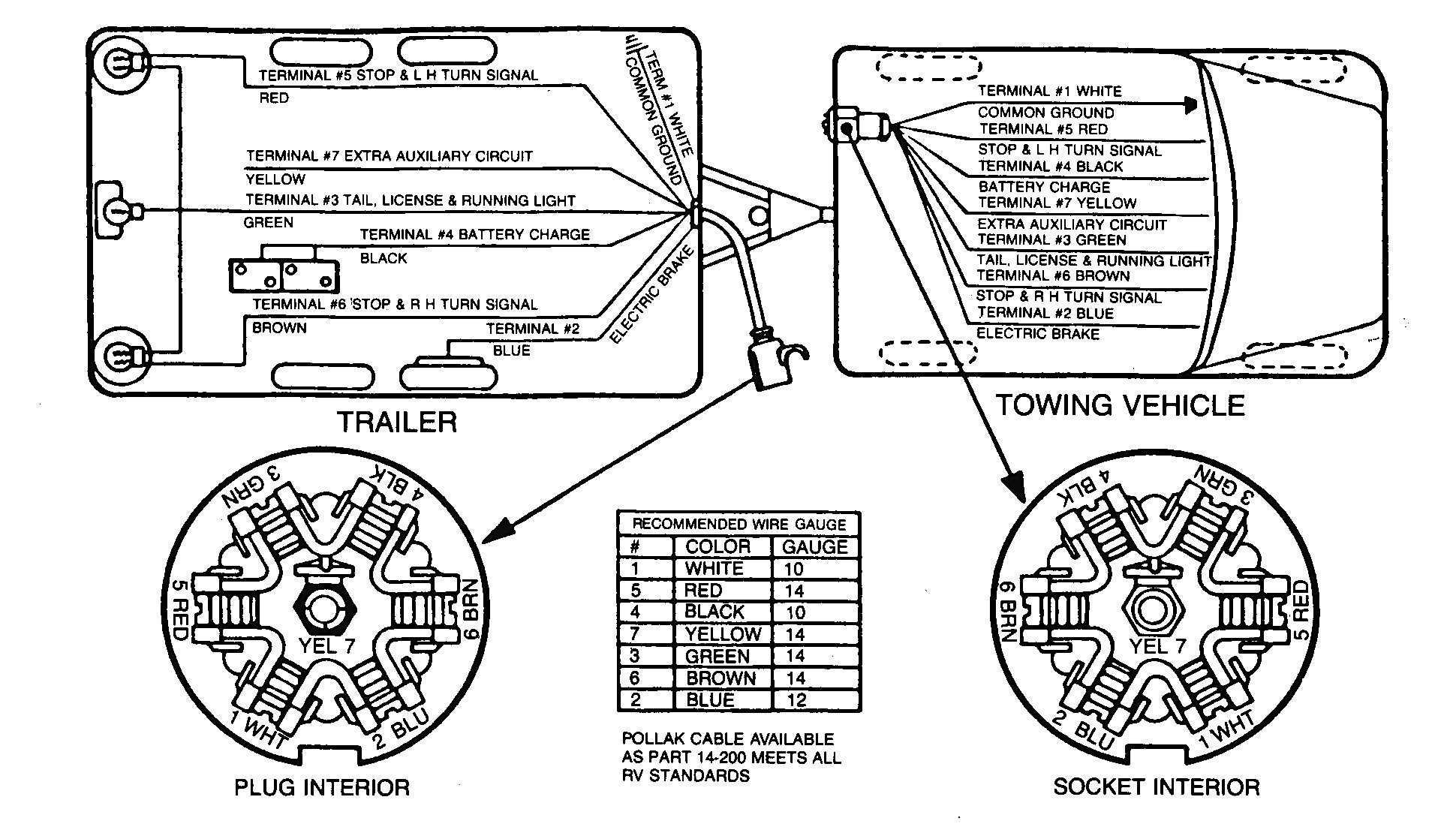
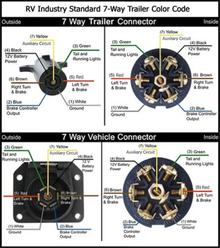
1 . White = Ground (See White Wire Notes below.) 2 . Brown = Tail Lights, Side Markers and Running Lights (See Brown Wire Notes below.) 3 . Yellow = Left Turn Signal & Left Brake Light 4 . Green = Right Turn Signal & Right Brake Light Please see the Trailer Wiring Diagram and Connector Application Chart below.
Wiring Diagram For Gooseneck Trailer Wiring Diagram Schemas
Trailer Wiring Diagram Not sure which wires attach to what on your trailer connectors? Does one of your turn signals not work and you're not sure which wire to inspect? Check out or trailer wiring diagrams for a quick reference on trailer wiring.
Caliber Gooseneck Trailer Wiring Diagram
A gooseneck trailer light diagram typically consists of several components, including the tow vehicle, trailer connector, trailer lights, and the necessary wiring. The tow vehicle connects to the trailer through a specific connector, such as a 7-pin or 4-pin connector.

trailer wiring diagrams Rvandplaya electrical wires Wiring Diagram ID
Since trailer manufacturers can sometimes use non-standard color wires for the taillight functions of their trailer it is best just to determine the function of each wire from your trailer's wiring and then wire it by function to the 7-way you end up getting.
Curt Trailer Wiring Diagram Gallery Wiring Diagram Sample
Expert Reply: Let's start at the brake assemblies/hubs on your new gooseneck trailer. The two wires coming from each assembly look exactly as they should. One wire will ground to the trailer frame and the other wire will attach to the brake output wire. The fact that you do not know which wire does what is absolutely okay!
Wiring Diagram For Gooseneck Trailer Wiring Diagram Schemas
Trailer Wiring Diagrams Trailer Wiring Connectors Various connectors are available from four to seven pins that allow for the transfer of power for the lighting as well as auxiliary functions such as an electric trailer brake controller, backup lights, or a 12V power supply for a winch or interior trailer lights.
Gooseneck Trailer Wiring Diagram Wiring Diagram
Download PDF manuals and diagrams for Diamond C Trailer components including Lippert, KTI, Hydrastar, and more. Skip to main content. Mobile Menu Close. Car Hauler; Equipment; Gooseneck; Pintle Hitch; Step Deck;. Single Wheel Triple Axle Gooseneck Trailer FMAX307. Tandem - Dual Wheel Gooseneck Trailer FMAX210. Tandem - Super Single Gooseneck.
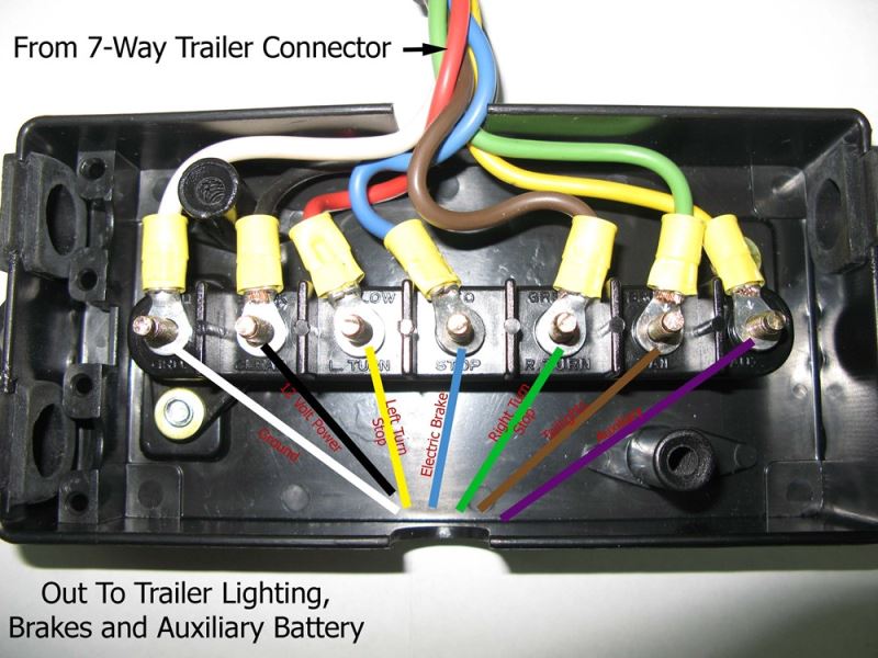
Wiring Diagram for Junction Box and/or Breakaway Kit on a Gooseneck
Like, Comment & Subscribe!*Did you know AI can find your next load?*🤖 https://dispatchrobot.ai/*Join the private Facebook group*📘 https://www.facebook.com/.
Flatbed Gooseneck Trailer Wiring Diagram wiring diagram creator
Gooseneck trailer wiring diagrams can be difficult to read, but once you understand how they are laid out, they become much easier to read. The diagrams are typically laid out in a grid-like pattern with the wires labeled in the left column and the connections labeled in the right column. The diagrams also typically show an illustration of the.